")
")

Micro structured optical arrays
Micro structured optical arrays (MOA) consist of a flat plate structured with parallel micro channels with a square cross section. Caused by reflection at the lateral walls of the channels a point source in a chosen distance in front of the optics will be imaged to a focal plane in the same distance behind the optics (fig. 1). MOA optics always provide a 1:1-imaging scale. The diameter of the focus spot is in the range of the diameter of the micro channels, normally in the range of >10 µm. MOAs can be constructed as holes in a plate (fig. 1, left side), or as a combination of two crossed gratings (fig. 1, right side). The second comes with the disadvantage that for instance the reflection in the horizontal direction occurs slightly before the reflection in the vertical direction, resulting in two different focal planes for the vertical and horizontal direction (astigmatism). This can be seen in figure 2, where the astigmatism leads to a larger focal spot diameter in the averaged focal plane (and two planes before and after with line foci).
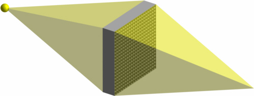
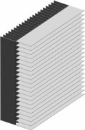
Fig. 1: Optical path in a micro channel plate optics (left) and second type of MOAs (right)
A simulation of the intensity distribution in the focal plane when illuminating using a point source shows -besides the focal point- a patterned intensity background with the same intensity level in that position when removing the optics. Additionally, there is a cross with an about ten times higher intensity level (fig. 2).
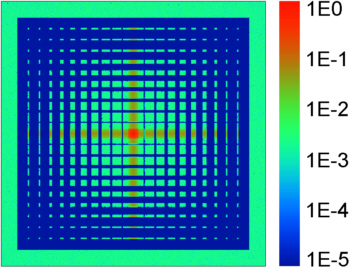
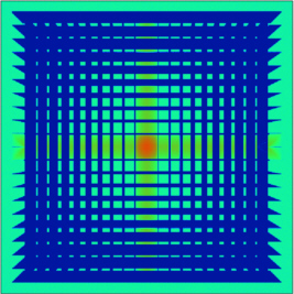
Fig. 2: Simulated intensity distribution of a micro channel plate with holes: the outer green frame is the intensity level without optics (left) and of a MOA consisting of two crossed gratings (right)
Lobster eye optics
Some species of the decapods (order shellfish), the group of the so-called long-bodied decapods, like lobster, prawn, crawfish and shrimp have eyes imaging light with reflecting micro channels (fig. 3) [Lan 1976]. This principle can be used for X-ray mirror optics as well [Ang 1979, Har 1980, Gru 2007].
The optics consists of a grid of micro channels each with a square cross-section. The entrance apertures of the channels are situated on a spherical surface and the individual channels point towards the centre of the sphere. Technically this type of optics is often realized by bending a micro channel plate in two directions. Light hitting the smooth side walls of the channels is reflected towards a focal point. The focal points are located on a sphere with roughly half the radius of the aperture sphere (cyan coloured line in fig. 4). The exact position depends on the geometry of the channels and on the distance of the light source.
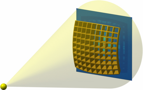
Fig. 3: Lobster eye optics: source (left), micro channel grid (gold colour) and detector plane with simulated intensity distribution (right, blue)
This optics provides a very large angle of field, theoretically it could image light from nearly any direction. As it uses total external reflection (TER), it is achromatic. For photon energies up to about 10 keV these optics works with reasonable efficiencies, but they can be used less effectively with much higher photon energies. The amount of light collected (and so the effective aperture) is limited by the photon energy dependent maximum TER angle, by the geometry of the channels and the roughness of the channel side walls. For a large field of view, a spherical detector surface is indispensable.

Fig. 4: Optical path in a lobster eye optics; on mouse-over  the lost rays are shown (gray: mirrors, cyan: detector, red: blocked or not hitting a mirror, blue: reflected twice, green: reflected three times)
A point source is focused to a spot far from being a point, see fig. 4 and 5. Only the part of the light reflected only once is directed to the focus. Some parts of the incoming beam will be lost because they hit the front edges of the mirrors or just miss all mirrors (rays close to the optical axis). Other rays are reflected more than once between the mirrors and so are lost for the imaging. Because of the large field of view, these rays can hardly be hindered from reaching the detector by e.g. inserting baffles. So this optics show an unwanted background, degrading the signal-to-noise ratio (SNR).
The most important application of lobster optics is their use in X-ray telescope satellite missions, where they are used to find interesting X-ray emitting objects. When an object has been detected, a large high resolution telescope (e.g. Wolter-optics) with its small angle of view is directed to the object to take high quality images.
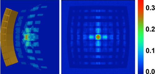
Fig. 5: Simulated intensity distribution in the focus of the lobster optics in fig. 1: side view (left) and front view (right)
| [Ang 1979] | J. R. P. Angel, Lobster Eyes as X-ray Telescopes, Astrophysical Journal, vol. 233, pp. 364-373, DOI: 10.1086/157397, 1979 |
| [Gru 2007] | V. Grubsky, M. Gertsenshteyn, T. Jannson, Nature-inspired optics enable omnidirectional and omnispectral imaging, SPIE Newsroom. DOI: 10.1117/2.1200702.0691, 4 April 2007 |
| [Har 1980] | B. K. Hartline, Lobster-Eye X-ray Telescope Envisioned, Science, vol. 207, no. 4426, p. 47, DOI: 10.1126/science.207.4426.47, 1980 |
| [Lan 1976] | M. F. Land, Superposition Images are Formed by Reflection in the Eyes of Some Oceanic Decapod Crustacea, Nature, vol. 263, issue 5580, pp. 764-765, DOI: 10.1038/263764a0, 1976 |